Total Pageviews

Monday, August 21, 2017

Revival and use the Arduino ESP8266 Wifi Shield Version 1.0 by Wang Tongze

   Some time ago (2015) I bought "Arduino ESP8266 Wifi Shield Version 1.0 by Wang Tongze" without more documentation... neither now 😕 Last year, I write an article in my language with this board, because I pressed and shuffled and firmware was erased... But let's start as normal condition...

   For normal operation mode switch must be in this position:
  In first tests, I connect Rx-Tx from this shield at Arduino Mega at Rx1-Tx1 pins, for see how work...
  I upload ESP8266_mega_serialtest.ino with 112500bps instead 9600bps (board is Arduino Mega, shield witj ESP8266 is just accessory)
   I open serial monitor window and I write some AT commands:
   You cand upload various sketches with ESP8266 chip controlled by Arduino.
   
   If you play with switches as me, with this configuration
and pus ESP-RST button, firmware will be erased... and this sheild not work, is just a piese untill you reflash the ESP8266 chip.
   I use info from article ESP8266: Reflash Dance! writted by Dave Vandenbout for classic ESP8266:
  Connect USB FTDI interface with 3.3V logic level as in photo
   Must push ESP-RST button and open software
  Find the COM used by USB interface
Change value in software
  Using BIN software button open files
  Using DOWNLOAD software button is write bin files in ESP8266 chip
  In software is writed procent
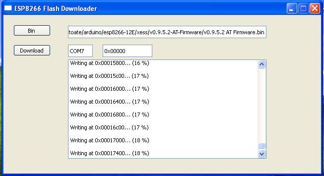
until is see
   Must change switch position in normal operation mode

   See ESP8266MOD shiled reflash movie, when I made exactlly as in descripription from above


Wednesday, July 12, 2017

0-30V/0-7A Power Supply Unit with LM723 and Arduino volt & ampermeter

original article (in romanian language)

   Dragos, known under albasete name from elforum (romanian electronic forum) made an useful power supply unit. Schemtic used by albasete is
   Original schemtic is from Reber electronic site (3A NAPAJALNIK NASTAVLJIV OD 1V DO 27V article). Also, I found same data in article 1V-27V 3A Variable DC Power Supply (http://powersupply33.com/).
  For measure voltage and current it use info from Arduino ca multimetru (3). It use existing resistor for measure current (R5) and add 2 resistor as divider resistor for measure voltage:
   Using original PCB board, I draw connexion to Arduino board:
   It use an Arduino nano board with i2c LCD1602 display, a active buzzer for indicate shortcircuit case. Also, I put DS18B20 temperature sensor and relay for power a cooler when tenmperature is bigger than a threshold level.
   For albasete version, I write psu_reber_ver3ro.ino sketch. In this sketch I put value for albasete case (R1 = 1k put between GND and A1 port, R2 = 39k put between +OUT and A1)
and value for threshold (temax) and hysteresis value (dete):
   Now, I put few photo pictures of realization progress:

   Dragos (albasete) send me a movie with PSU in tests: 0-30V/0-7A PSU with LM723 and Arduino volt & ampermeter

Saturday, May 6, 2017

Dynamic lights with CMOS integrated

   A few few years ago (in 1995), Tehnium magazine publish an article send by me 😀 (then I was a young student) in nr. 1/1995 (see magazine).
   Schematic was inspired by article from Tehnium anual magazine 1990, but my schematic have extra ligts "games":

   A few time ago (3-4 years) I need a simple schematic for automatic dynamic games without microcontrollers, so I remenber my schematic... but I simplify my schematic to eliminate useless states, so new schematic is
   I maded the schematic on test board:
   I made few movie with this schematic, in my language, but lights made without language 😇, so, I reccomand you to see at nest movies:
joc de lumini cu 4 canale
joc de lumini cu 4 canale (2)
joc de lumini cu 4 canale (3)
joc de lumini cu 4 canale (4)

Monday, May 1, 2017

Gear Shift Indicator

   For car tunning enthusiastic like my friend George I design a Gear Shift Indicator based on my old article when use just keys, diodes, few resistors and 7-segment display. Now, I use TLE4905L hall sensors instead simple keys (push buttons) and Arduino board.
   Schematic is simple:
  If you upload my GearShift_1.ino sketch, on display you can see:
- P for parking
- 1 for first gear:
- 2 for second gear
- 3 for third gear
- 4 for fourth gear
- 5 go fifth
- 6 for sixth gear
- 0 flashing for reverse gear
- nothing for unknown state:
  You can see George's movie (without sound 😎) named Gear Shift Indicator with first test in workshop:

Tuesday, April 25, 2017

Arduino clock on TM1637 display

    I found a cheap led display some time ago, with TM1637 chip, has 4 digit 7-segment and 2 leds for seconds, so, I decided to made a clock using DS3231 RTC module clock:
   I use a simple schematic for this clock:
   Using TM1637_DS3231_clock0.ino sketch, my clock work as a .. clock :))) like in movie named Arduino clock with DS3231 on TM1637 display
   For hour litle than 10, on display we see 09
so, I change to simple 9
just changing few lines in sketch (TM1637_DS3231_cloc0a.ino).
   In Arduino clock with DS3231 on TM1637 display (2) movie, you cand see the diference on display and in sketch....
   Next step was to put an encoder (KY-040) to change hours and minutes, schematic is:
(also, I put an speaker/buzzer from PC between D7 and GND).
   For change hours, must long push (2-3 seconds) the push button from encoder, and you will see
so, must rotate clocwise to increase value or rotate antioclockwire (trigonometric sense) to decrease value for hour. When hour has desired value must push on button from encoder to enter in mode to change minutes:
   Procedure is similar, and after change value for minutes must push on button from encoder to enter in usual mode, as a claock.
    TM1637_DS3231_clock1.ino sketch must be used for have a clock like in my description or in Arduino clock with DS3231 on TM1637 display (3) movie:
27.04.2017
   This clock can be use also with DS1307 instead DS3231, just need a small change:
so, TM1637_DS3231_clock1a.ino have this chenage and few other for correct few bugs... in Arduino clock with DS3231 on TM1637 display (4)
PS: with last change, you can use DS1307 or DS3231 RTC clock module, without other modifcation.

Thursday, February 16, 2017

3.95" Raspberry Pi display on Arduino Due

   I find a big display: 3.95" = 10cm: original use is for Raspbbery Pi board, but I put at Arduino Due development board because work like RPi with 3.3V logical level voltage... If I (or you) want to use with classical Arduino board (Uno, Mega, Nano, etc) must add two CD4060 chips (hex noninverting buffer)
 or buy another display with  logical interface and made as shield for Arduino board:
   After I talk with Vlad who use Arduino Nano and than Mega, I made next schematic:
    After I was documented, I use MCUFRIEND_kbv library with one example (single who works):
   I tested with good resuls using Arduino IDE 1.6.0, 1.6.6 and 1.8.0 software version on different PC with Windows XP or Windows 10.
   In test the display in Cristhmas period, so I put adequate texts:
  I made some movies, but I recommand you just: