original article


This display was received from Janos Baricz, vintage things passionate. On webworld, we find just some info and tests with FDS-132 display who is bigger than FDS-125.
So, you can see info about "big brother" at:
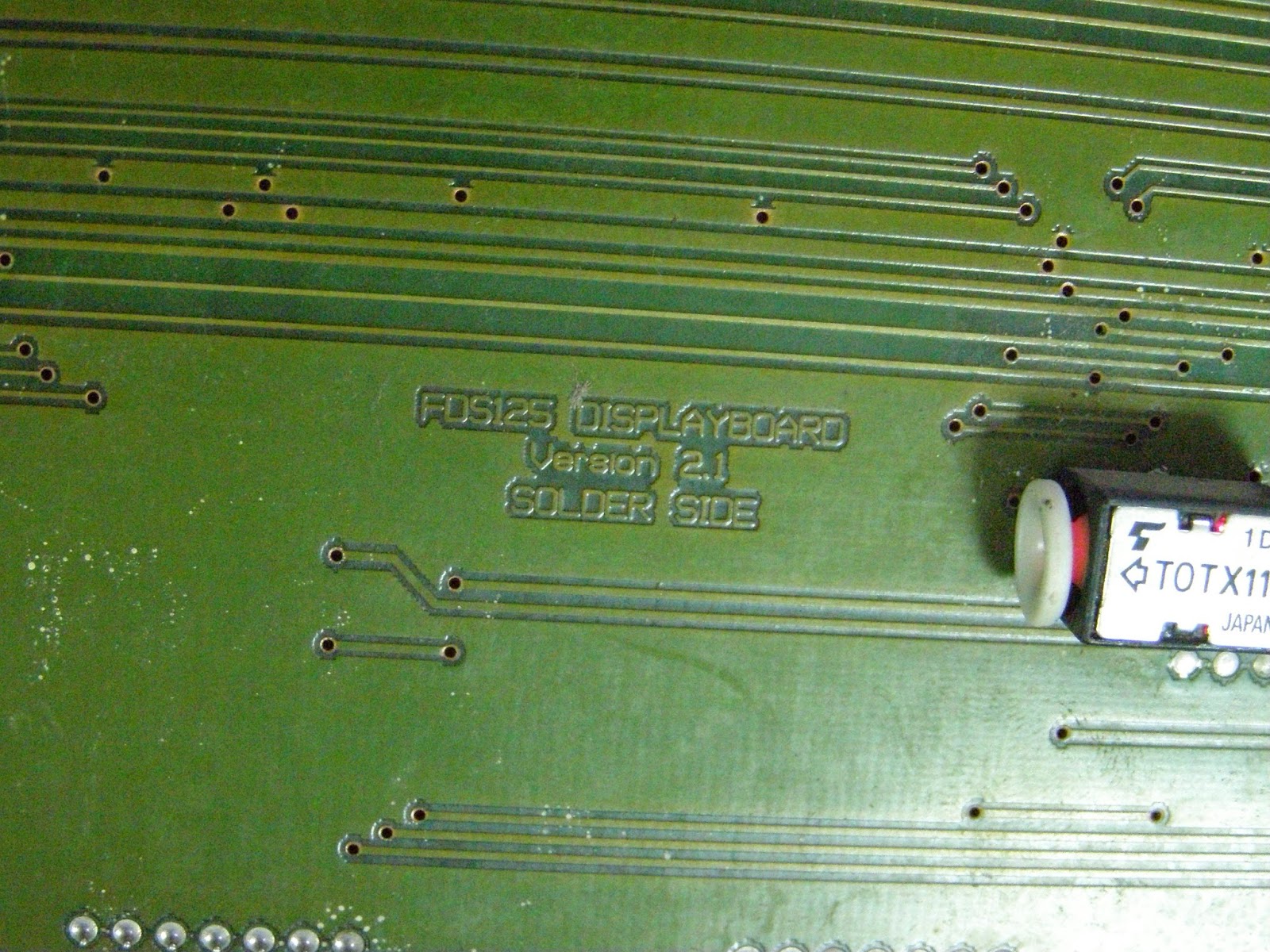
FDS-125 display has 2 big rows, each with 7 rows and 60 columns (12 matrix 5x7 leds) controlled by Lattice MACH21 microcontroller.
For control by Arduino must extract Lattice MAC21 microntroller and put few wires like in this pictures from arduinows.blogspot.com:


Janos made hardware part for this display:


and in this case, situation is:
- green wire is A from FDS-125 display, must connect to D5 pin at Arduino board
- green wire is A from FDS-125 display, must connect to D5 pin at Arduino board
- pink wire is B from FDS-125 display, must connect to D6 pin at Arduino board
- white wire is C from FDS-125 display, must connect to D7 pin at Arduino board
- yellow wire is STROBE from FDS-125 display, must connect to D10 pin at Arduino board
- mauve wire is DATA from FDS-125 display, must connect to D11 pin at Arduino board
- grey wire is CLOCK from FDS-125 display, must connect to D13 pin at Arduino board
- blue wire is RESRED from FDS-125 display, must connect to D9 pin at Arduino board
- black wire is GND from FDS-125 display, must connect to GND pin at Arduino board
Also, on the back site is power for display (in picture is a red wire connected from power conector at power of display part).


I redesigned connexion between FDS-125 display and Arduino board:

After that, I tested some sketches and I "lit" the display

I put an RTC clock made with DS3231 (works fine with DS1307, also) and adapt an sketch from arduinoforum.nl made for FDS-132. Result is FDS125_clock.ino sketch and test schematic is:

Whem upload the sketch on display is on top row is data and on bottom row is hour:

Also, I made Arduino clock on FDS-125 display movie to see how clock is..