Total Pageviews

Showing posts with label am2302. Show all posts

Wednesday, November 30, 2016

Another adjusting clock with alarm, hygrometer & thermometer on 1.8" ST7735 display

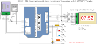
   I use feature from article Another adjusting clock with alarm & thermometer using DS3231 on 1.8" ST7735 display and change reading internal temperature of DS3231 with DHT22 senzor (AM2302), but you can use a cheaper and not very precise DHT11 senzor.
   Schematic is now:
   My test montage is
   By using educ8stv_rtctft160_alarm_dht.ino or much better educ8stv_rtctft160_alarm_eeprom_dht.ino sketch, on display you can see: name of day, date, hour clock, hour alarm, temperature and humidity
   In another adjusting clock with alarm, thermometer & hygrometer using DS3231 on 1.8" ST7735 display you can see info on display and hoe change/adjust hour, data, hour alarm, activate and deactivate alarm, etc:
   Alse, I made another movie, named another adjusting clock with alarm, thermometer & hygrometer using DS3231 on 1.8" ST7735 display (2), where I try to explain more detailed the feature of this clock...

Friday, August 12, 2016

Itron FG209M2 vfd display controlled by Arduino via 2 MAX6921

see about this article on HACKADAY ;)


   I give for tests an old vfd display made by Itron with 20 characters each made with 14 segments, point & comma.
   Janos, who is owner of this vfd display, made a interface with 2 MAX6921 integrated, using this schematic:
and PCB board is
   I redesigned schematic of vfd interface using Eagle PCB software
   After I study the datasheet of MAX6921, for send data to vfd display, classical style is:
 but in my case is little different because I have cascaded 2 MAX6921; for put on vfd display letter R on left corner must send this data:
with this notation of segments of character:
   For initial test, I made a simple schematic, using fist time an Arduino Mega board, than Arduino Uno:
   When upload VFD_FG209M2_2MAX6921_test1.ini sketch I see X letter moving from right to left of vfd display, like in video named 

   I made small steps (create characters, like in application note for MAX6954 (see https://www.maximintegrated.com/en/app-notes/index.mvp/id/3211)
 until I simulate a clock with calendar and temperature and humidity using VFD_FG209M2_2MAX6921_test3j3c.ini sketch, see movie named afisaj VFD FG209M2 cu MAX6921 si Arduino (9)

   Finally, I put in schematic an RTC module with DS3231 (works fine with DS1307, too) and DHT22 module (AM2302 sensor + 4k7 resistor between +5V and DATA pin) for humidity and temperature:
   Using RTC_DHT_VFD_FG209M2_2MAX6921_ver4.ino I have on vfd display next texts:
   Because texts are in my native language (roumanian) I made few changes for have alternative indications:
NOTE: More details about steps in experiments can be writte in original article !

   I reduce previous sketch and remain just english text for day & day, current sketch is RTC_DHT_VFD_FG209M2_2MAX6921_ver4b.ino and you can see how is now in movie named clock on VFD FG209M2 display with MAX6921 and Arduino (3)

1-March-2021
   I received from Janos new info for display
also I received the schematic for power the VFD:

Friday, July 3, 2015

SDA5708: 8 character 7x5 dot matrix LED display

original article !

   Recently, I received as gift, for tests, a special display named SDA5708. This display was used in old sat receiver Nokia DBOX1 and is,like in title, with 8 character made, each, with 7x5 dot display led.
   After I received this display, I search technical info about this display and I found some:
http://www.bralug.de/wiki/Display_SDA5708
http://www.sbprojects.com/knowledge/footprints/sda5708/index.php
http://blog.smue.org/archives/433-DBOX1-SDA5708-display-+-arduino.html 
   Using info from second article, I redesigned connection schematic:
   I made a schematic using info from 3rd article:
and after I upload the changed example sketch, on display I can see:
I made few changes in example sketch, for display my ID used on net:
   After this first step, I put an AM2302 with 4k7 rezistor (same as DHT22 sensor) for read temperature and humidity info:
and I change the sketch for see:
   Result are good and I put an RTC clock module made with DS3231 and momentary switch like in schematic:

and I can see, after I write sketch named SDA5708_DHT22_ceas_simplu.ino:
   Now, I can go to nest level, a full weather station with adjusting clock usin rotary encoder.
   I made this schematic:
   After I write a full sketch named SDA5708_DHT22_ceas_encoder_v1m2.ino, cyclic, on display I can see:
- clock:
- temerature and relative humidity:
   After a short push, I can see the data (day.mounth.year):
   After a long push (3-4 seconds), I can d change the data:
- year:
- month:
- day:
- hour:
- minutes:
   I made a movie, named weather station with adjusting clock on SDA5708 display where you can see more than I write: