First, I tested classical sketch named i2_scanner but I received no device or error at all adresses beginning with 0x01.
I search on internet and I found an interesting article STM32 I2C SCANNER. Because informations from there are too much and must read carefully, I change directly Arduino mega with STM32F103. I saw logo info on display and than nothing. I realised STM32 send correctly i2c comands to device, ut not understand messages from any device. LCD1602 (or LCD2004) need just commands, so can be used.
I tested with LCD1602 powered from external 5V and STM32 board with 3.3V fron USB-FTDI interface or through USB using internal voltage regulator.
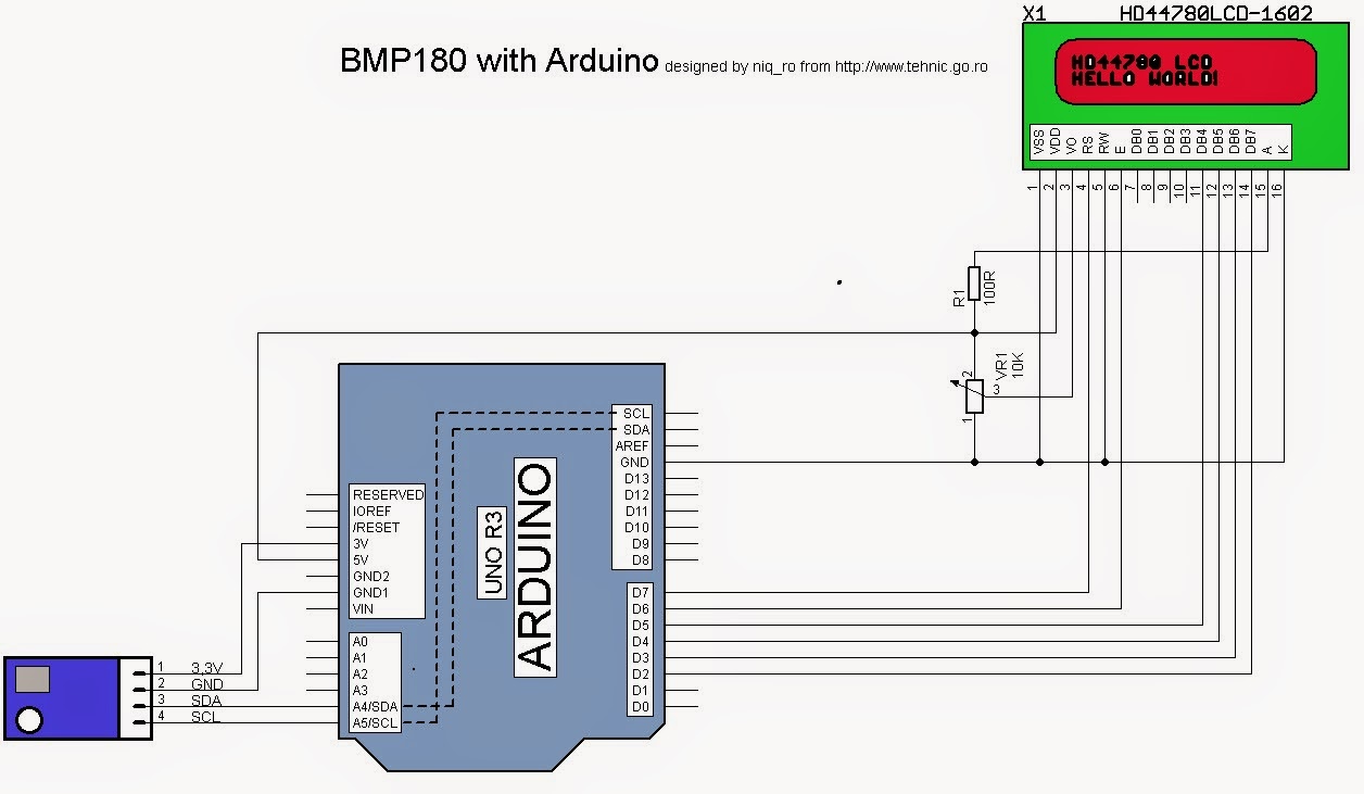
For a stand alone weather station with information about temperature and presure, I put a alphanumeric LCD display with 16 colons and 2 rows (1602):
and test montage is:
I use this sketch:
// adapted sketch by niq_ro from http://nicuflorica.blogspot.ro/ & http://arduinotehniq.blogspot.com/// https://github.com/adafruit/Adafruit-BMP085-Library
#include <Wire.h>
#include <Adafruit_BMP085.h>
/*************************************************** This is an example for the BMP085 Barometric Pressure & Temp Sensor Designed specifically to work with the Adafruit BMP085 Breakout ----> https://www.adafruit.com/products/391 These displays use I2C to communicate, 2 pins are required to interface Adafruit invests time and resources providing this open source code, please support Adafruit and open-source hardware by purchasing products from Adafruit! Written by Limor Fried/Ladyada for Adafruit Industries. BSD license, all text above must be included in any redistribution ****************************************************/// Connect VCC of the BMP085 sensor to 3.3V (NOT 5.0V!)// Connect GND to Ground// Connect SCL to i2c clock - on '168/'328 Arduino Uno/Duemilanove/etc thats Analog 5// Connect SDA to i2c data - on '168/'328 Arduino Uno/Duemilanove/etc thats Analog 4// EOC is not used, it signifies an end of conversion// XCLR is a reset pin, also not used here// include the library code:
#include <LiquidCrystal.h>
// initialize the library with the numbers of the interface pinsLiquidCrystal lcd(7, 6, 5, 4, 3, 2);
/* ------------------- | LCD | Arduino | ------------------- LCD RS pin to digital pin 7 | RS | D7 | LCD Enable pin to digital pin 6 | E | D6 | LCD D4 pin to digital pin 5 | D4 | D6 | LCD D5 pin to digital pin 4 | D5 | D4 | LCD D6 pin to digital pin 3 | D6 | D3 | LCD D7 pin to digital pin 2 | D7 | D2 | LCD R/W pin to ground | R/W | GND | -------------------*/
Adafruit_BMP085 bmp;
voidsetup() {
lcd.begin(16, 2);
// Print a logo message to the LCD.
lcd.print("www.tehnic.go.ro");
lcd.setCursor(0, 1);
lcd.print("creat de niq_ro");
delay (2500);
lcd.clear();
// Print another message to the LCD.
lcd.setCursor(2, 0);
lcd.print("termometru -");
lcd.setCursor(0, 1);
lcd.print("barometru ver1.0");
delay (2500);
lcd.clear();
Serial.begin(9600);
if (!bmp.begin()) {
Serial.println("nu exita senzor compatibil BMP085 sau BMP180");
while (1) {}
}
}
voidloop() {
Serial.print("Temperatura = ");
Serial.print(bmp.readTemperature());
Serial.println(" *C");
Serial.print("Presiune = ");
Serial.print(bmp.readPressure());
Serial.print(" Pa / ");
// Serial.print("Presiune = ");float presiune1 = bmp.readPressure()/101.325;
presiune1 = presiune1 * 0.760;
Serial.print(presiune1);
Serial.println(" mmHg");
// Calculate altitude assuming 'standard' barometric// pressure of 1013.25 millibar = 101325 PascalSerial.print("Altitudine = ");
Serial.print(bmp.readAltitude());
Serial.println(" m");
Serial.print("Presiune la nivelul marii (calculata) = ");
Serial.print(bmp.readSealevelPressure());
Serial.print(" Pa / ");
// http://en.wikipedia.org/wiki/Atmospheric_pressure#Mean_sea_level_pressure// Serial.print("Presiure la nivelul marii (calculata) = ");float presiune = bmp.readSealevelPressure()/101.325;
presiune = presiune * 0.760;
Serial.print(presiune);
Serial.println(" mmHg");
// you can get a more precise measurement of altitude// if you know the current sea level pressure which will// vary with weather and such. If it is 1015 millibars// that is equal to 101500 Pascals.Serial.print("Altitudine reala = ");
Serial.print(bmp.readAltitude(101500));
Serial.println(" m");
Serial.println();
lcd.setCursor(1, 0);
lcd.print("temp.= ");
if ( bmp.readTemperature() < 10)
{
lcd.print(" ");
lcd.print(bmp.readTemperature());
}
else
{
lcd.print(bmp.readTemperature(),1);
}
lcd.write(0b11011111);
lcd.print("C ");
lcd.setCursor(1, 1);
lcd.print("pres.= p");
lcd.print(presiune,0);
lcd.print("mmHg ");
delay(2500);
}
24.11.2014 In last weak-end, I received 3 pics from Dave (http://g4rvh.wordpress.com/) with a shield for Arduino Uno, made after my schematic:
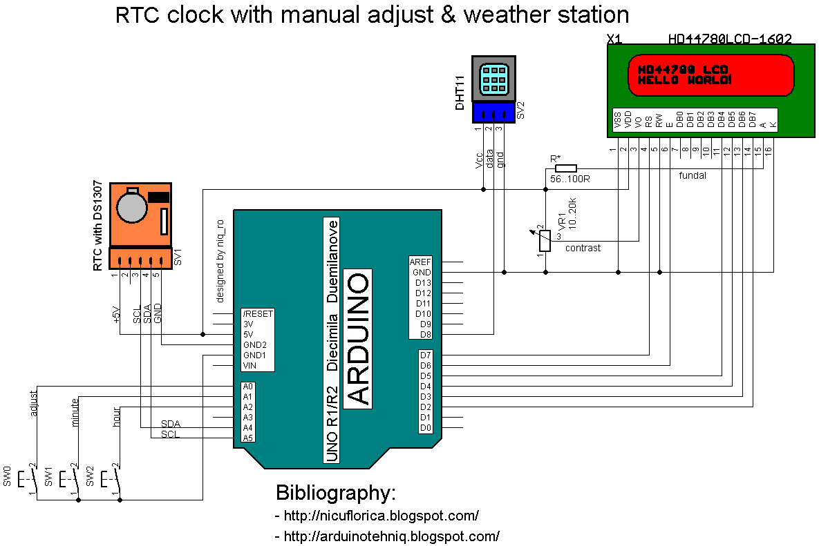
A simple weather station give us temperature & humidity + time. I use a Arduino Uno board as "brain", a DHT11 sensor for humidity and temperature & RTC module with DS1307 for time and values are put on a alphanumeric LCD1602 display. My last schematic is:
Practically, my montage is:
I use this sketch:
// Date and time functions using a DS1307 RTC // original sketck from http://learn.adafruit.com/ds1307-real-time-clock-breakout-board-kit/// add part with SQW=1Hz from http://tronixstuff.wordpress.com/ & http://www.bristolwatch.com/arduino/arduino_ds1307.htm// adapted sketch by niq_ro from http://nicuflorica.blogspot.ro/// original article from http://nicuflorica.blogspot.ro/2013/06/ceas-de-timp-real-rtc-cu-ds1307-si.html
#include <Wire.h>
#include "RTClib.h"// include the library code:
#include <LiquidCrystal.h>
// initialize the library with the numbers of the interface pinsLiquidCrystal lcd(7, 6, 5, 4, 3, 2);
/* ------------------- | LCD | Arduino | ------------------- LCD RS pin to digital pin 7 | RS | D7 | LCD Enable pin to digital pin 6 | E | D6 | LCD D4 pin to digital pin 5 | D4 | D6 | LCD D5 pin to digital pin 4 | D5 | D4 | LCD D6 pin to digital pin 3 | D6 | D3 | LCD D7 pin to digital pin 2 | D7 | D2 | LCD R/W pin to ground | R/W | GND | -------------------*/RTC_DS1307 RTC;
#include <DHT.h>
#define DHTPIN 8 // what pin we're connected DHT11
#define DHTTYPE DHT11 // DHT 11
DHT dht(DHTPIN, DHTTYPE);
byte SW0 = A0;
byte SW1 = A1;
byte SW2 = A2;
// use for hexa in zecimal conversionint zh, uh, ore;
int zm, um, miniti;
voidsetup () {
// DHT init
dht.begin();
// set up the LCD's number of columns and rows:
lcd.begin(16, 2);
// Print a logo message to the LCD.
lcd.print("www.tehnic.go.ro");
lcd.setCursor(0, 1);
lcd.print("creat de niq_ro");
delay (2500);
lcd.clear();
// Serial.begin(9600);Wire.begin();
// part code from http://tronixstuff.wordpress.com/Wire.beginTransmission(0x68);
Wire.write(0x07); // move pointer to SQW addressWire.write(0x10); // sends 0x10 (hex) 00010000 (binary) to control register - turns on square waveWire.endTransmission();
// end part code from http://tronixstuff.wordpress.com/
RTC.begin();
if (! RTC.isrunning()) {
//Serial.println("RTC is NOT running!");// following line sets the RTC to the date & time this sketch was compiled
RTC.adjust(DateTime(__DATE__, __TIME__));
}
pinMode(SW0, INPUT); // for this use a slide switchpinMode(SW1, INPUT); // N.O. push button switchpinMode(SW2, INPUT); // N.O. push button switchdigitalWrite(SW0, HIGH); // pull-ups ondigitalWrite(SW1, HIGH);
digitalWrite(SW2, HIGH);
}
voidloop () {
DateTimenow = RTC.now();
int h = dht.readHumidity();
int t = dht.readTemperature();
lcd.setCursor(4, 0);
if ( now.hour() < 10)
{
lcd.print(" ");
lcd.print(now.hour(), DEC);
}
else
{
lcd.print(now.hour(), DEC);
}
lcd.print(":");
if ( now.minute() < 10)
{
lcd.print("0");
lcd.print(now.minute(), DEC);
}
else
{
lcd.print(now.minute(), DEC);
}
lcd.print(":");
if ( now.second() < 10)
{
lcd.print("0");
lcd.print(now.second(), DEC);
}
else
{
lcd.print(now.second(), DEC);
}
lcd.print(" ");
lcd.setCursor(1, 1);
// lcd.print("t=");if ( t < 10)
{
lcd.print(" ");
lcd.print(t);
}
else
{
lcd.print(t);
}
//lcd.print(",0");
lcd.write(0b11011111);
lcd.print("C");
/* lcd.setCursor(0, 1); if ( now.day() < 10) { lcd.print("0"); lcd.print(now.day(), DEC); } else { lcd.print(now.day(), DEC); } lcd.print("/"); if ( now.month() < 10) { lcd.print("0"); lcd.print(now.month(), DEC); } else { lcd.print(now.month(), DEC); } lcd.print("/"); lcd.print(now.year(), DEC); lcd.print(" "); */
lcd.setCursor(10, 1);
// lcd.print("H=");
lcd.print(h);
lcd.print("%RH");
if (!(digitalRead(SW0))) set_time(); // hold the switch to set timedelay(500);
}
void set_time() {
byte minutes1 = 0;
byte hours1 = 0;
byte minutes = 0;
byte hours = 0;
while (!digitalRead(SW0)) // set time switch must be released to exit
{
minutes1=minutes;
hours1=hours;
while (!digitalRead(SW1)) // set minutes
{
minutes++;
// converting hexa in zecimal:
zh = hours / 16;
uh = hours - 16 * zh ;
ore = 10 * zh + uh;
zm = minutes / 16;
um = minutes - 16 * zm ;
miniti = 10 * zm + um;
/* for(int i = 20 ; i >0 ; i--) { displayNumber01(ore*100+miniti); } */
lcd.setCursor(4, 0);
if ( ore < 10)
{
lcd.print(" ");
lcd.print(ore);
}
else
{
lcd.print(ore);
}
lcd.print(":");
if ( miniti < 10)
{
lcd.print("0");
lcd.print(miniti);
}
else
{
lcd.print(miniti);
}
lcd.print(":");
lcd.print("00");
if ((minutes & 0x0f) > 9) minutes = minutes + 6;
if (minutes > 0x59) minutes = 0;
Serial.print("Minutes = ");
if (minutes >= 9) Serial.print("0");
Serial.println(minutes, HEX);
delay(150);
}
while (!digitalRead(SW2)) // set hours
{
hours++;
// converting hexa in zecimal:
zh = hours / 16;
uh = hours - 16 * zh ;
ore = 10 * zh + uh;
zm = minutes / 16;
um = minutes - 16 * zm ;
miniti = 10 * zm + um;
/* for(int i = 20 ; i >0 ; i--) { displayNumber01(ore*100+miniti); } */
lcd.setCursor(4, 0);
if ( ore < 10)
{
lcd.print(" ");
lcd.print(ore);
}
else
{
lcd.print(ore);
}
lcd.print(":");
if ( miniti < 10)
{
lcd.print("0");
lcd.print(miniti);
}
else
{
lcd.print(miniti);
}
lcd.print(":");
lcd.print("00");
if ((hours & 0x0f) > 9) hours = hours + 6;
if (hours > 0x23) hours = 0;
Serial.print("Hours = ");
if (hours <= 9) Serial.print("0");
Serial.println(hours, HEX);
delay(150);
}
Wire.beginTransmission(0x68); // activate DS1307Wire.write(0); // where to beginWire.write(0x00); //secondsWire.write(minutes); //minutesWire.write(0x80 | hours); //hours (24hr time)Wire.write(0x06); // Day 01-07Wire.write(0x01); // Date 0-31Wire.write(0x05); // month 0-12Wire.write(0x09); // Year 00-99Wire.write(0x10); // Control 0x10 produces a 1 HZ square wave on pin 7. Wire.endTransmission();
// converting hexa in zecimal:
zh = hours / 16;
uh = hours - 16 * zh ;
ore = 10 * zh + uh;
zm = minutes / 16;
um = minutes - 16 * zm ;
miniti = 10 * zm + um;
/* for(int i = 20 ; i >0 ; i--) { displayNumber01(ore*100+miniti); } // delay(150); */
lcd.setCursor(4, 0);
if ( ore < 10)
{
lcd.print(" ");
lcd.print(ore);
}
else
{
lcd.print(ore);
}
lcd.print(":");
if ( miniti < 10)
{
lcd.print("0");
lcd.print(miniti);
}
else
{
lcd.print(miniti);
}
lcd.print(":");
lcd.print("00");
}
Like in previous article, if you want to change time, must push and hold SW0 (adjust) switch and display is change on 0:00, then push SW2 (hour) or SW1 (minute) repeatedly until time is ok, after this realise SW0, and time is put in RTC.