I buy an small 1.8" TFT display with ST7735B driver and I try to connect directly to Arduino Uno board as I see on net... but result was not good... display is almost white
and just disconnect accidentaly the GND I can see something...
So, I search on Arduino forums and on net (article INSTRUCTABLES: Arduino TFT display and font library ) and I found a solution like Nokia 5110 monochrome display .. I put 1k resistor on each data pins to Arduino to display:
and I tested more Arduino library for this display with ST7735 driver (from Adafruit, TFT library, ucglib library, etc) and I made move to see .. movie is named ST7735B display with Arduino board
and after I push MENU/OK button, on display is undervoltage thereshold, who cand change with + & - buttons:
After I push MENU button, value is stored in EEPROM memory, on display is overvoltage thereshold, who can be change by + & - buttons:
after push again MENU button, value is stored in EEPROM memory, on display is delay-off tine in second for reconnect coil relay after voltage inoutside range:
31.07.2020
I added a sketch to use LCD1602 alphanumerica display on i2c connexion instead existing display (with MAX7219 and 7-segment led display). Sketch is main_supply_emonlib_under_overvoltage_ver4.ino !
After I made a test for Measuring AC Main Supply Voltage with Arduino, now I change the sketch for made protection relay with adjustable limits for undervoltage, overvoltage and delay-off time using 3 buttons:
After power the module, Arduino read and calculate vltage for AC main power supply and if is ok, coil relay is powered:
If push MENU/OK button, on display is SET
after 2-3 seconds, on display is undervoltage threshold, who cand change using + & - buttons:
After you push MENU/OK button, is displayed overvoltage thereshold, who cand change using + & - buttons:
After you pus MENU/OK buttons on display is delay-off time for reconnect coil relay after voltage is outside good range, also you can change value form 1 tp 20 seconds using + & - buttons:
After you push MENU/OK button, on display is main voltage:
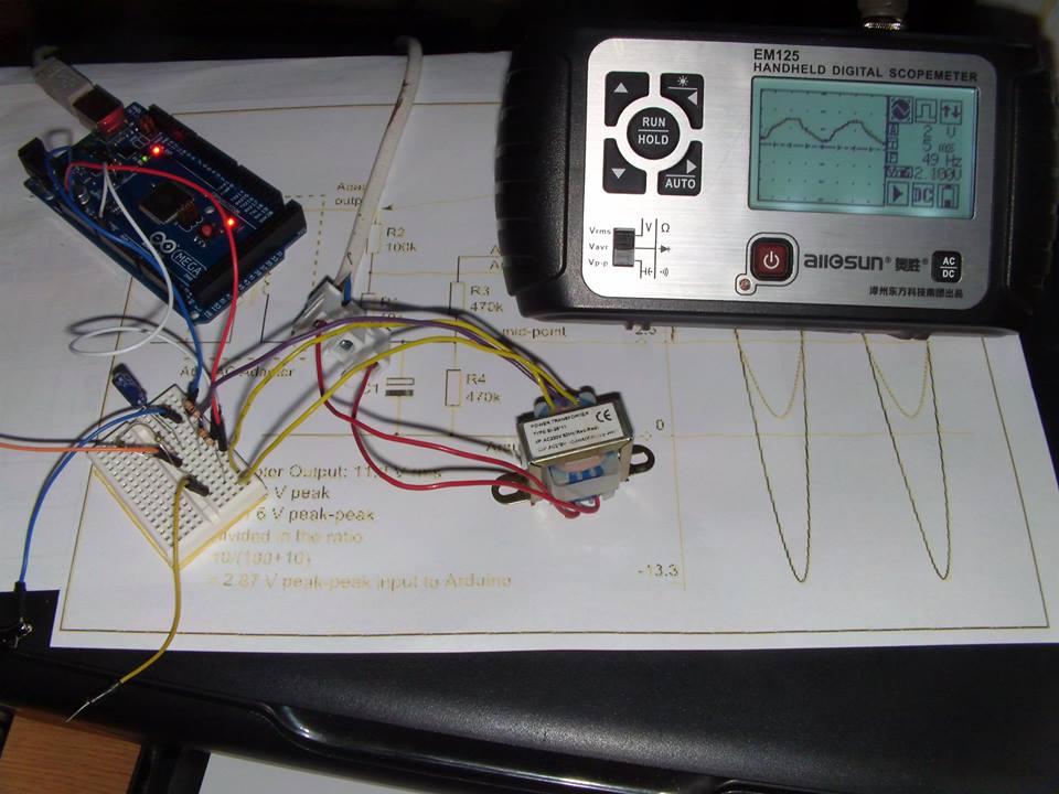
If you need to measuring AC main supply voltage with Arduino must made some calculation.
I use a simple schematic:
I can directly measure the DC voltage on R1 resistor. I use internal reference from Arduino Uno board (compatible board with ATmega328 microcontroller) so maximum value for U2 can be
U2 = U1*(R1+R2)/R1 = 1.1*(1+22)/1=25.3V
AC voltage U1 so DC voltage U2 = U1*1.41-Udiode
If we put value in equation
U1 = (U2+Udiode)/1.41
because I use trafo U0 = k * U1.
For tests, I use a trafo imprinted 220V/2x12V 200mA but if I measeure voltage from secondary coil
I found 11V when main voltage is 220V, so k = 220/11=20. I use an 1N4007 diode and Udiode=0.65V.
I made a system for home acces with delay-off using keypad from outside and push button from inside. I write a sketch for use actuator or solenoid.
In stand by mode, solenoid (or actuator) is released.
After I indroduce good code *1234# from keypad actuator is unlocked for 0.7 seconds; about 5 seconds acces is permited, after that actuator is locked for 0.7 seconds. Same cases are when push button from inside.
If you use solenoid instead actuator, after I introduce good code *1234# from keypad coil solenoid is powered about 5 seconds, after that coil solenoid is released.
Base test schematic is: