Total Pageviews

Tuesday, September 27, 2016

Measuring AC Main Supply Voltage with Arduino (2)

   In article named Measuring AC Voltage with an AC to AC power adapter from OpenEnergyMonitor I found a interesting solution for measure AC voltage.
   Schematic is
   I use EmonLib library like in article:
   On DSO I see on R1 resistor
and at A2 input of Arduino board (on R4 resistor):
   I use an LED display with 8 digit 7-segment drived by MAX7219 (I present on article namend Modul de afisare cu 8 cifre LED din 7 segmente fiecare controlate de MAX7219
   I use some configuration for LedControl library (dosc at The Arduino LedControl library):
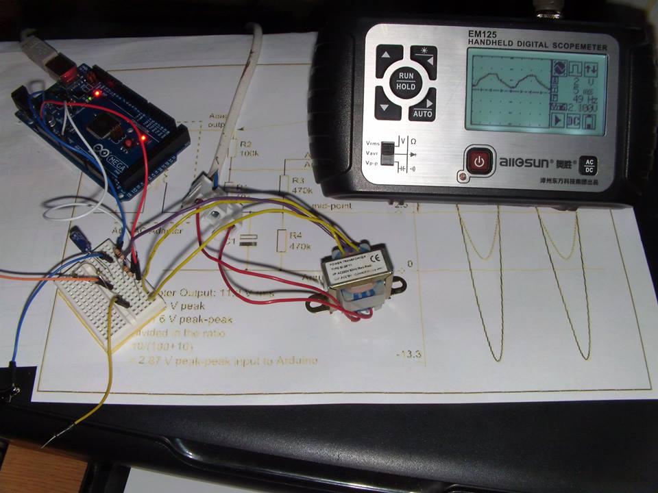
   Test schematic is
   I write main_voltage_emonlib_1.ino sketch and upload in Arduino board:

Measuring AC Main Supply Voltage with Arduino

   If you need to measuring AC main supply voltage with Arduino must made some calculation.
   I use a simple schematic:
   I can directly measure the DC voltage on R1 resistor. I use internal reference from Arduino Uno board (compatible board with ATmega328 microcontroller) so maximum value for U2 can be
U2 = U1*(R1+R2)/R1 = 1.1*(1+22)/1=25.3V
  AC voltage U1 so DC voltage U2 = U1*1.41-Udiode
  If we put value in equation
U1 = (U2+Udiode)/1.41
because I use trafo U0 = k * U1.
  For tests, I use a trafo imprinted 220V/2x12V 200mA but if I measeure voltage from secondary coil
I found 11V when main voltage is 220V, so k = 220/11=20. I use an 1N4007 diode and Udiode=0.65V.
  I use an LED display with 4 digit 7-segment drived by TM1637 (who I present on base blog in article named Afisaj cu 4 cifre controlate de TM1637 si Arduino and sketches are at https://github.com/tehniq3/TM1637-display):
   Schematic for display put on Arduino Uno is:
   I write main-voltage_0.ino sketch and upload in Arduino board and I made a movie named main supply voltage measured with Arduino

Monday, September 26, 2016

Home acces using keypad from outside and push button from inside

   I made a system for home acces with delay-off using keypad from outside and push button from inside. I write a sketch for use actuator or solenoid.
   In stand by mode, solenoid (or actuator) is released.
   After I indroduce good code *1234# from keypad actuator is unlocked for 0.7 seconds; about 5 seconds acces is permited, after that actuator is locked for 0.7 seconds. Same cases are when push button from inside.
   If you use solenoid instead actuator, after I introduce good code *1234# from keypad coil solenoid is powered about 5 seconds, after that coil solenoid is released.
   Base test schematic is:
but if you use actuator, schematic is
and if you use solenoid, schematic is
   A comrade, Tommy, made a permanent montage on PCB for actuator:
   I put an alphanumeric LCD1602 display on i2c and an RTC module with DS3231 (or DS1307) and base schematic is:
   If you upload acces_code_keypad_3.ino sketch. in standby mode, on display is hour & date:
and when acces is shared and a open padlock is displayed.
   In movie named door lock acces with code and pushbutton you cand see all I write:

Friday, August 12, 2016

Itron FG209M2 vfd display controlled by Arduino via 2 MAX6921

see about this article on HACKADAY ;)


   I give for tests an old vfd display made by Itron with 20 characters each made with 14 segments, point & comma.
   Janos, who is owner of this vfd display, made a interface with 2 MAX6921 integrated, using this schematic:
and PCB board is
   I redesigned schematic of vfd interface using Eagle PCB software
   After I study the datasheet of MAX6921, for send data to vfd display, classical style is:
 but in my case is little different because I have cascaded 2 MAX6921; for put on vfd display letter R on left corner must send this data:
with this notation of segments of character:
   For initial test, I made a simple schematic, using fist time an Arduino Mega board, than Arduino Uno:
   When upload VFD_FG209M2_2MAX6921_test1.ini sketch I see X letter moving from right to left of vfd display, like in video named 

   I made small steps (create characters, like in application note for MAX6954 (see https://www.maximintegrated.com/en/app-notes/index.mvp/id/3211)
 until I simulate a clock with calendar and temperature and humidity using VFD_FG209M2_2MAX6921_test3j3c.ini sketch, see movie named afisaj VFD FG209M2 cu MAX6921 si Arduino (9)

   Finally, I put in schematic an RTC module with DS3231 (works fine with DS1307, too) and DHT22 module (AM2302 sensor + 4k7 resistor between +5V and DATA pin) for humidity and temperature:
   Using RTC_DHT_VFD_FG209M2_2MAX6921_ver4.ino I have on vfd display next texts:
   Because texts are in my native language (roumanian) I made few changes for have alternative indications:
NOTE: More details about steps in experiments can be writte in original article !

   I reduce previous sketch and remain just english text for day & day, current sketch is RTC_DHT_VFD_FG209M2_2MAX6921_ver4b.ino and you can see how is now in movie named clock on VFD FG209M2 display with MAX6921 and Arduino (3)

1-March-2021
   I received from Janos new info for display
also I received the schematic for power the VFD:

Thursday, July 21, 2016

FM radio with RDA5807


   A FM radio with RDS info and digital volume can be made with RDA5807 module, who is similar as TEA5767 (pcb board & pins).
   For easy connexion, I made a adapter board from 2mm distance pins to 2.54mm:
   I found a russian article with fm radio who use RDA5807 chisp at http://full-chip.net/arduino-proekty/97-cifrovoy-fm-priemnik-na-arduino-i-module-rda5807-s-graficheskim-displeem-i-funkciey-rds.html
 
with this schematic:
   In this article is a movie named RDA5807 ФМ приемник на ARDUINO

  In russian sketch I found some words in spanish language and after few search I see article Arduino Radio RDA5807 con RDS LCD Nokia 3310
   I made some changes in sketch for optimal display of frequence value (my sketch is put on my Github channel - RDA5807_fmradio_3buttons_ver0.ino) for use with my configuration:
  I made few test without audio amplifier:
after that, I put PC speaker at radio module, see RDA5807 FM radio with RDS info on Nokia 5110 display using Arduino (3) movie:
   In I push MENU button, the cases are:
- AUTOMATIC SHEARCH:
- INFO:
- MANUAL SEARCH:
- VOLUME (16 steps, from 0 to 15):
   I made some changes in sketch and now frequency and step volume are stored in EEPROM memory, see RDA5807_fmradio_3buttons_ver1.ino, see results in next movie: RDA5807 FM radio with RDS info on Nokia 5110 display using Arduino (4)