In previous article I made a simple Arduino Chriostmas tree on breadboard with 9 leds, now I use a big piece of cardboard and cutter... I use 21 recovered leds (old leds) on 17 channels (I put 2 red leds in series) as in this schematic
I use Arduino Nono board with ATmega168 because sketch is small (see christmas_tree_17channels.ino), but hase interesting effects (random leds lite, random delay between commands, random leds off), as in Carton Christmas tree with leds movie:
After the Christmas tree was adorned I made new movies:
I write 2 sketches, first (christmas_lights_1.ino) chose random the led for power on, wait 50ms, chose random the led for power off, second sketch (christmas_lights_1a.ino) is like first, just change time wirtting as be random from 10 to 100ms.
I tested an (retired now) WeMos D1 development board made with ESP8266EX microcontroller. About this board I found some info at https://www.wemos.cc/product
For easy use as other Arduino boards, is ok to see this picture:
Last project with this board is a Web Switch Control.
This sketch made a webserver using AJAX style (static page and just some datas is changes).
My sketch led_controlled_from_webpage.ino has some change line, but I use same password (1234), and my led is at GPIO5 (D15/SCL) and GND (I not put 220-470 ohms resistor limiter, but is more good to put). I use 8087 port, but you can change to 80.
After I tested about one mounth, I see some problemes, when wi-fi router is disconnected and reconnect.. so, I study but I give a tip from a collaborator, Mircea Craciun, who indicate my another post from ESP8266 forum.
I put an LED for wi-fi error at GPIO12 (D12/MISO) and GND.
At first start, after restart or if link between router and WeMos is broken, second led blink until link with wi-fi is ok. You can see in ESP8266 Switch control with autoreconnect to wi-fi network movie how WeMos D1 board is working.
At http://www.esp8266.com/wiki/doku.php?id=arduino-docs I found how I can use EEPROM memory from ESP8266EX microcontroller for store the state of led (ON or OFF) and number of good clicks (just for see how work the system).
In previous article I present you how can conect an FDS-125 display to Arduino and how mase a simple, but "static" clock style
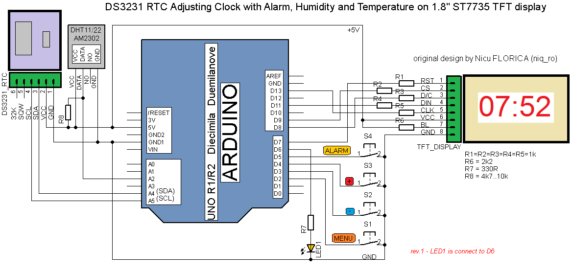
For made an "dynamic" clock, I use some schematic
I write in exitting sketch to display name of day in week in 2 language (romanian who is my navitve language and in english). It easy to change in your navive language by writting name of days in one line:
Is very important to have in same subdyrectory of sketch font75.h file like in this picture:
So, by uploading FDS125_clock1b.ino sketch, you cand see on display new info, beside date:
Because, DHT sensor is too slow when is reading, I made some changes to see temperature and humidity in same times, also I chege font75.h file to display degree symbol instead ':
This display was received from Janos Baricz, vintage things passionate. On webworld, we find just some info and tests with FDS-132 display who is bigger than FDS-125.
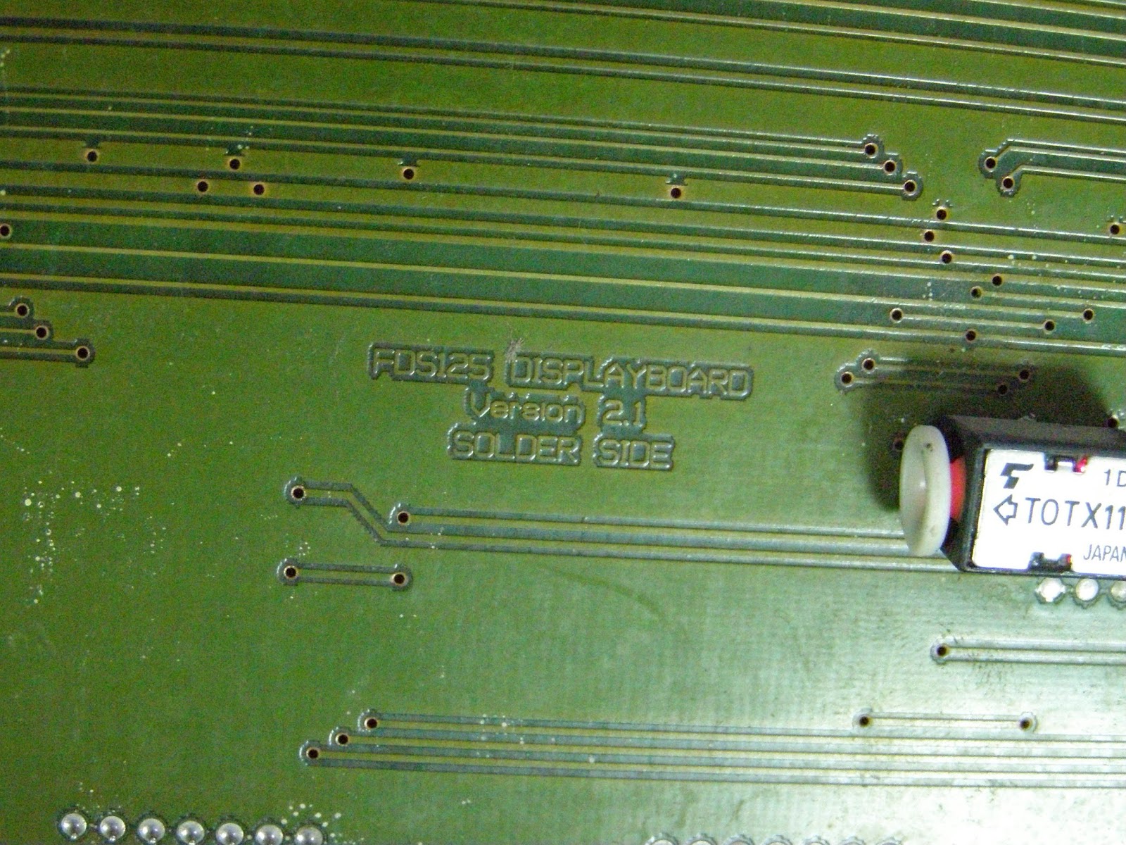
FDS-125 display has 2 big rows, each with 7 rows and 60 columns (12 matrix 5x7 leds) controlled by Lattice MACH21 microcontroller.
For control by Arduino must extract Lattice MAC21 microntroller and put few wires like in this pictures from arduinows.blogspot.com:
Janos made hardware part for this display:
and in this case, situation is:
- green wire is A from FDS-125 display, must connect to D5 pin at Arduino board
- pink wire is B from FDS-125 display, must connect to D6 pin at Arduino board
- white wire is C from FDS-125 display, must connect to D7 pin at Arduino board
- yellow wire is STROBE from FDS-125 display, must connect to D10 pin at Arduino board
- mauve wire is DATA from FDS-125 display, must connect to D11 pin at Arduino board
- grey wire is CLOCK from FDS-125 display, must connect to D13 pin at Arduino board
- blue wire is RESRED from FDS-125 display, must connect to D9 pin at Arduino board
- black wire is GND from FDS-125 display, must connect to GND pin at Arduino board
Also, on the back site is power for display (in picture is a red wire connected from power conector at power of display part).
I redesigned connexion between FDS-125 display and Arduino board:
After that, I tested some sketches and I "lit" the display
I put an RTC clock made with DS3231 (works fine with DS1307, also) and adapt an sketch from arduinoforum.nl made for FDS-132. Result is FDS125_clock.ino sketch and test schematic is:
Whem upload the sketch on display is on top row is data and on bottom row is hour: