Total Pageviews

Monday, September 29, 2014

Weather station & manual adjust for RTC clock with Arduino and alphanumeric LCD1602 display

   A simple weather station give us temperature & humidity + time.
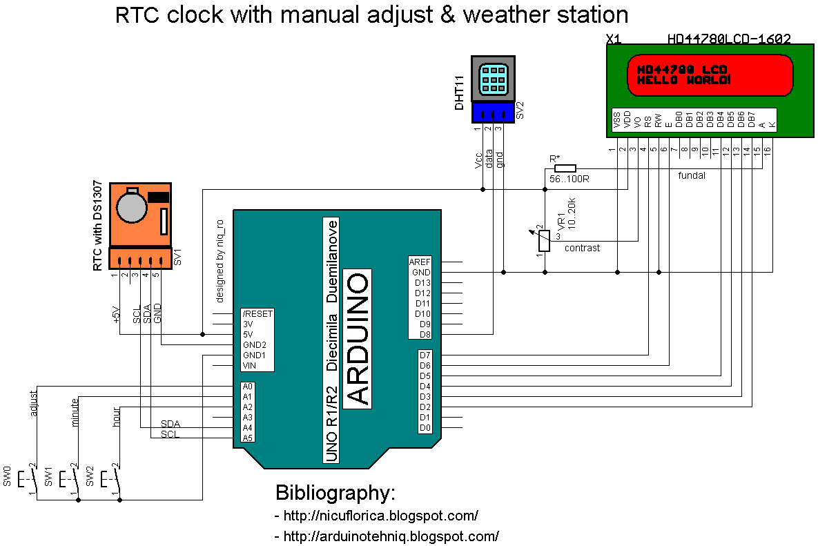
   I use a Arduino Uno board as "brain", a DHT11 sensor for humidity and temperature & RTC module with DS1307 for time and values are put on a alphanumeric LCD1602 display.
   My last schematic is:
   Practically, my montage is:
   I use this sketch:
// Date and time functions using a DS1307 RTC 
// original sketck from http://learn.adafruit.com/ds1307-real-time-clock-breakout-board-kit/
// add part with SQW=1Hz from http://tronixstuff.wordpress.com/ & http://www.bristolwatch.com/arduino/arduino_ds1307.htm
// adapted sketch by niq_ro from http://nicuflorica.blogspot.ro/
// original article from http://nicuflorica.blogspot.ro/2013/06/ceas-de-timp-real-rtc-cu-ds1307-si.html

#include <Wire.h>
#include "RTClib.h"

// include the library code:
#include <LiquidCrystal.h>
// initialize the library with the numbers of the interface pins
LiquidCrystal lcd(7, 6, 5, 4, 3, 2);

/*                                    -------------------
                                      |  LCD  | Arduino |
                                      -------------------
 LCD RS pin to digital pin 7          |  RS   |   D7    |
 LCD Enable pin to digital pin 6      |  E    |   D6    |
 LCD D4 pin to digital pin 5          |  D4   |   D6    |
 LCD D5 pin to digital pin 4          |  D5   |   D4    |
 LCD D6 pin to digital pin 3          |  D6   |   D3    |
 LCD D7 pin to digital pin 2          |  D7   |   D2    |
 LCD R/W pin to ground                |  R/W  |   GND   |
                                      -------------------
*/

RTC_DS1307 RTC;

#include <DHT.h>
#define DHTPIN 8     // what pin we're connected DHT11
#define DHTTYPE DHT11   // DHT 11 
DHT dht(DHTPIN, DHTTYPE);

byte SW0 = A0;
byte SW1 = A1;
byte SW2 = A2;

// use for hexa in zecimal conversion
int zh, uh, ore;
int zm, um, miniti;


void setup () {
  // DHT init
  dht.begin();
  // set up the LCD's number of columns and rows: 
  lcd.begin(16, 2);
  // Print a logo message to the LCD.
  lcd.print("www.tehnic.go.ro");  
  lcd.setCursor(0, 1);
  lcd.print("creat de niq_ro");
  delay (2500);
  lcd.clear();
    
   // Serial.begin(9600);
    Wire.begin();
  
// part code from http://tronixstuff.wordpress.com/
Wire.beginTransmission(0x68);
Wire.write(0x07); // move pointer to SQW address
Wire.write(0x10); // sends 0x10 (hex) 00010000 (binary) to control register - turns on square wave
Wire.endTransmission();
// end part code from http://tronixstuff.wordpress.com/

    RTC.begin();
  if (! RTC.isrunning()) {
    //Serial.println("RTC is NOT running!");
    // following line sets the RTC to the date & time this sketch was compiled
    RTC.adjust(DateTime(__DATE__, __TIME__));
  }

 pinMode(SW0, INPUT);  // for this use a slide switch
  pinMode(SW1, INPUT);  // N.O. push button switch
  pinMode(SW2, INPUT);  // N.O. push button switch

  digitalWrite(SW0, HIGH); // pull-ups on
  digitalWrite(SW1, HIGH);
  digitalWrite(SW2, HIGH);

}

void loop () {
   DateTime now = RTC.now();
  int h = dht.readHumidity();
  int t = dht.readTemperature();

   lcd.setCursor(4, 0);
   if ( now.hour() < 10)
   {
     lcd.print(" "); 
     lcd.print(now.hour(), DEC);
   }
   else
   {
   lcd.print(now.hour(), DEC);
   }
   lcd.print(":");
   if ( now.minute() < 10)
   {
     lcd.print("0"); 
     lcd.print(now.minute(), DEC);
   }
   else
   {
   lcd.print(now.minute(), DEC);
   }
   lcd.print(":");
   if ( now.second() < 10)
   {
     lcd.print("0"); 
     lcd.print(now.second(), DEC);
   }
   else
   {
   lcd.print(now.second(), DEC);
   }
     lcd.print(" "); 
 
  lcd.setCursor(1, 1);
  // lcd.print("t=");
    if ( t < 10)
   {
     lcd.print(" "); 
     lcd.print(t);
   }
   else
   {
   lcd.print(t);
   }
   //lcd.print(",0");
   lcd.write(0b11011111);
   lcd.print("C");
    
/*   lcd.setCursor(0, 1);
    if ( now.day() < 10)
   {
     lcd.print("0"); 
     lcd.print(now.day(), DEC);
   }
   else
   {
   lcd.print(now.day(), DEC);
   }
   lcd.print("/");
   if ( now.month() < 10)
   {
     lcd.print("0"); 
     lcd.print(now.month(), DEC);
   }
   else
   {
   lcd.print(now.month(), DEC);
   }
   lcd.print("/");
   lcd.print(now.year(), DEC);
   lcd.print(" "); 
*/  
   lcd.setCursor(10, 1);
  // lcd.print("H=");
   lcd.print(h);
   lcd.print("%RH");
 
   if (!(digitalRead(SW0))) set_time(); // hold the switch to set time

 
   delay(500);
}

void set_time()   {
  byte minutes1 = 0;
  byte hours1 = 0;
  byte minutes = 0;
  byte hours = 0;

  while (!digitalRead(SW0))  // set time switch must be released to exit
  {
    minutes1=minutes;
    hours1=hours;
    
     
    while (!digitalRead(SW1)) // set minutes
    { 
     minutes++;  
   // converting hexa in zecimal:
    zh = hours / 16;
    uh = hours - 16 * zh ;
    ore = 10 * zh + uh; 
    zm = minutes / 16;
    um = minutes - 16 * zm ;
    miniti = 10 * zm + um; 
  
  /*  
     for(int i = 20 ; i >0  ; i--) {
     displayNumber01(ore*100+miniti); 
     }
   */
   lcd.setCursor(4, 0);
   if ( ore < 10)
   {
     lcd.print(" "); 
     lcd.print(ore);
   }
   else
   {
   lcd.print(ore);
   }
   lcd.print(":");
   if ( miniti < 10)
   {
     lcd.print("0"); 
     lcd.print(miniti);
   }
   else
   {
   lcd.print(miniti);
   }
   lcd.print(":");
   lcd.print("00"); 
      
      if ((minutes & 0x0f) > 9) minutes = minutes + 6;
      if (minutes > 0x59) minutes = 0;
      Serial.print("Minutes = ");
      if (minutes >= 9) Serial.print("0");
      Serial.println(minutes, HEX);
    delay(150);    
    }

    while (!digitalRead(SW2)) // set hours
    { 
     hours++;          
     
   // converting hexa in zecimal:
    zh = hours / 16;
    uh = hours - 16 * zh ;
    ore = 10 * zh + uh; 
    zm = minutes / 16;
    um = minutes - 16 * zm ;
    miniti = 10 * zm + um; 
    
   /*
     for(int i = 20 ; i >0  ; i--) {
     displayNumber01(ore*100+miniti); 
     }
   */
   lcd.setCursor(4, 0);
   if ( ore < 10)
   {
     lcd.print(" "); 
     lcd.print(ore);
   }
   else
   {
   lcd.print(ore);
   }
   lcd.print(":");
   if ( miniti < 10)
   {
     lcd.print("0"); 
     lcd.print(miniti);
   }
   else
   {
   lcd.print(miniti);
   }
   lcd.print(":");
   lcd.print("00");
      
      if ((hours & 0x0f) > 9) hours =  hours + 6;
      if (hours > 0x23) hours = 0;
      Serial.print("Hours = ");
      if (hours <= 9) Serial.print("0");
      Serial.println(hours, HEX);
    delay(150);
    }

    Wire.beginTransmission(0x68); // activate DS1307
    Wire.write(0); // where to begin
    Wire.write(0x00);          //seconds
    Wire.write(minutes);          //minutes
    Wire.write(0x80 | hours);    //hours (24hr time)
    Wire.write(0x06);  // Day 01-07
    Wire.write(0x01);  // Date 0-31
    Wire.write(0x05);  // month 0-12
    Wire.write(0x09);  // Year 00-99
    Wire.write(0x10); // Control 0x10 produces a 1 HZ square wave on pin 7. 
    Wire.endTransmission();
  
    // converting hexa in zecimal:
    zh = hours / 16;
    uh = hours - 16 * zh ;
    ore = 10 * zh + uh; 
    zm = minutes / 16;
    um = minutes - 16 * zm ;
    miniti = 10 * zm + um; 
    
   /*  for(int i = 20 ; i >0  ; i--) {
     displayNumber01(ore*100+miniti); 
     }
 //  delay(150);
    */

   lcd.setCursor(4, 0);
   if ( ore < 10)
   {
     lcd.print(" "); 
     lcd.print(ore);
   }
   else
   {
   lcd.print(ore);
   }
   lcd.print(":");
   if ( miniti < 10)
   {
     lcd.print("0"); 
     lcd.print(miniti);
   }
   else
   {
   lcd.print(miniti);
   }
   lcd.print(":");
   lcd.print("00");
}
   I made a movie with some usefull comments, named weather & manual adjust for RTC clock with Arduino and LCD1602 display:
   Like in previous article, if you want to change time, must push and hold SW0 (adjust) switch and display is change on 0:00, then push SW2 (hour) or SW1 (minute) repeatedly until time is ok, after this realise SW0, and time is put in RTC.

Friday, September 26, 2014

Manual adjust for RTC clock with Arduino and 7-segment LED display

   For a good clock must use a RTC (real-time clock) like DS1307. For Arduino enthusiasts and hobbylist exists some RTC module with DS1307, but you can made yourself a good RTC module like me.
   Original schematic is from DS1307 datasheet, but I redesigned schematic using freeversion of Eagle PCB Software:
   Note: Battery is CR2032, like in schematic... in boards is a little error

   A full schematic for RTC clock with Arduino is:

   Compared to other schematics that can adjust time (reset clock at 0:00, adjust hours and minutes). Original schematic, design and sketch is from article Using Arduino with a DS1307 Real Time Clock by Lewis Loflin.
   If you want to change time, must push and hold S3 (adjust) switch and display is change on 0:00, then push S1 (hour) or S2 (minute) repeatedly until time is ok, after this realise S3, and time is put in RTC.
   I use a multiplexed 4-digit 7-segment display with common anode same in article named Arduino UNO running 4-digit 7-segment display from http://www.hobbytronics.co.uk/. Is a unusual schematic, but works fine; a usual schematic use resistors for current limit.
   My sketch is:
/*
 4 digit 7 segment display: http://www.sparkfun.com/products/9483
 Datasheet: http://www.sparkfun.com/datasheets/Components/LED/7-Segment/YSD-439AR6B-35.pdf
 7 segments + 4 digits + 1 colon = 12 pins required for full control 
 */
// modified connexion by niq_ro from http://nicuflorica.blogspot.com
// for my Luckylight KW4-563ASA
// dataseet: http://www.tme.eu/ro/Document/dfc2efde2e22005fd28615e298ea2655/KW4-563XSA.pdf

int digit1 = 11; //PWM Display pin 12 (digit1 is common anonds A1 from right side)
int digit2 = 10; //PWM Display pin 9 (digit2 is  common A2)
int digit3 = 9; //PWM Display pin 8 (digit3 is common anods A3)
int digit4 = 6; //PWM Display pin 6 (digit4 is common anods, from left side)

//Pin mapping from Arduino to the ATmega DIP28 if you need it
//http://www.arduino.cc/en/Hacking/PinMapping
int segA = 2; //Display pin 11
int segB = 3; //Display pin 7
int segC = 4; //Display pin 4
int segD = 5; //Display pin 2
int segE = 12; //Display pin 1
int segF = 7; //Display pin 10
int segG = 8; //Display pin 5
int segDP = 13; // Display pin 3

#include <Wire.h>
#include "RTClib.h"
RTC_DS1307 RTC;

// Date and time functions using a DS1307 RTC connected via I2C and Wire lib
// original sketck from http://learn.adafruit.com/ds1307-real-time-clock-breakout-board-kit/
// add part with SQW=1Hz from http://tronixstuff.wordpress.com/2010/10/20/tutorial-arduino-and-the-i2c-bus/
// add part with manual adjust http://www.bristolwatch.com/arduino/arduino_ds1307.htm

byte SW0 = A0; byte SW1 = A1; byte SW2 = A2; // use for hexa in zecimal conversion int zh, uh, ore; int zm, um, miniti; void setup() {     // Serial.begin(57600);   Wire.begin();   RTC.begin(); // RTC.adjust(DateTime(__DATE__, __TIME__)); // if you need set clock... just remove // from line above this // part code for flashing LED Wire.beginTransmission(0x68); Wire.write(0x07); // move pointer to SQW address // Wire.write(0x00); // turns the SQW pin off  Wire.write(0x10); // sends 0x10 (hex) 00010000 (binary) to control register - turns on square wave at 1Hz // Wire.write(0x13); // sends 0x13 (hex) 00010011 (binary) 32kHz Wire.endTransmission();   if (! RTC.isrunning()) {     Serial.println("RTC is NOT running!");     // following line sets the RTC to the date & time this sketch was compiled     RTC.adjust(DateTime(__DATE__, __TIME__));   }       // dht.begin();   pinMode(segA, OUTPUT);   pinMode(segB, OUTPUT);   pinMode(segC, OUTPUT);   pinMode(segD, OUTPUT);   pinMode(segE, OUTPUT);   pinMode(segF, OUTPUT);   pinMode(segG, OUTPUT);   pinMode(segDP, OUTPUT);   pinMode(digit1, OUTPUT);   pinMode(digit2, OUTPUT);   pinMode(digit3, OUTPUT);   pinMode(digit4, OUTPUT);    //  pinMode(13, OUTPUT);  Serial.begin(9600);  Serial.println("test for niq_ro");  pinMode(SW0, INPUT); // for this use a slide switch   pinMode(SW1, INPUT); // N.O. push button switch   pinMode(SW2, INPUT); // N.O. push button switch   digitalWrite(SW0, HIGH); // pull-ups on   digitalWrite(SW1, HIGH);   digitalWrite(SW2, HIGH); } void loop() { digitalWrite(segDP, HIGH);   DateTime now = RTC.now();   int timp = now.hour()*100+now.minute(); //   int timp = (now.minute(), DEC); //   displayNumber(12); // this is number to diplay //   int timp = 1234;   Serial.print(now.hour(), DEC);   Serial.print(":");   Serial.print(now.minute(), DEC);   Serial.print(" -> ");   Serial.print(timp);   Serial.println(" !"); // display parts       for(int i = 250 ; i >0 ; i--) {      if (timp >= 1000) displayNumber01(timp);      else displayNumber02(timp);    }     for(int i = 250 ; i >0 ; i--) {      if (timp >= 1000) displayNumber03(timp);      else displayNumber04(timp);    }    if (!(digitalRead(SW0))) set_time(); // hold the switch to set timevoid set_time() {   byte minutes1 = 0;   byte hours1 = 0;   byte minutes = 0;   byte hours = 0;   while (!digitalRead(SW0)) // set time switch must be released to exit   {     minutes1=minutes;     hours1=hours;                while (!digitalRead(SW1)) // set minutes     {       minutes++;      // converting hexa in zecimal:     zh = hours / 16;     uh = hours - 16 * zh ;     ore = 10 * zh + uh;      zm = minutes / 16;     um = minutes - 16 * zm ;     miniti = 10 * zm + um;            for(int i = 20 ; i >0 ; i--) {      displayNumber01(ore*100+miniti);       }              if ((minutes & 0x0f) > 9) minutes = minutes + 6;       if (minutes > 0x59) minutes = 0;       Serial.print("Minutes = ");       if (minutes >= 9) Serial.print("0");       Serial.println(minutes, HEX);     delay(150);     }     while (!digitalRead(SW2)) // set hours     {       hours++;                    // converting hexa in zecimal:     zh = hours / 16;     uh = hours - 16 * zh ;     ore = 10 * zh + uh;      zm = minutes / 16;     um = minutes - 16 * zm ;     miniti = 10 * zm + um;            for(int i = 20 ; i >0 ; i--) {      displayNumber01(ore*100+miniti);       }                  if ((hours & 0x0f) > 9) hours = hours + 6;       if (hours > 0x23) hours = 0;       Serial.print("Hours = ");       if (hours <= 9) Serial.print("0");       Serial.println(hours, HEX);     delay(150);     }     Wire.beginTransmission(0x68); // activate DS1307     Wire.write(0); // where to begin     Wire.write(0x00); //seconds     Wire.write(minutes); //minutes     Wire.write(0x80 | hours); //hours (24hr time)     Wire.write(0x06); // Day 01-07     Wire.write(0x01); // Date 0-31     Wire.write(0x05); // month 0-12     Wire.write(0x09); // Year 00-99     Wire.write(0x10); // Control 0x10 produces a 1 HZ square wave on pin 7.     Wire.endTransmission();        // converting hexa in zecimal:     zh = hours / 16;     uh = hours - 16 * zh ;     ore = 10 * zh + uh;      zm = minutes / 16;     um = minutes - 16 * zm ;     miniti = 10 * zm + um;            for(int i = 20 ; i >0 ; i--) {      displayNumber01(ore*100+miniti);       }  // delay(150);        }    } void displayNumber01(int toDisplay) { #define DISPLAY_BRIGHTNESS  500 #define DIGIT_ON  HIGH #define DIGIT_OFF  LOW   for(int digit = 4 ; digit > 0 ; digit--) {     //Turn on a digit for a short amount of time     switch(digit) {     case 1:      digitalWrite(digit1, DIGIT_ON);      digitalWrite(segDP, HIGH);       break;    case 2:       digitalWrite(digit2, DIGIT_ON);       digitalWrite(segDP, LOW);       break;     case 3:       digitalWrite(digit3, DIGIT_ON);       digitalWrite(segDP, HIGH);       break;     case 4:       digitalWrite(digit4, DIGIT_ON);       digitalWrite(segDP, HIGH);       break;     }     lightNumber(toDisplay % 10);     toDisplay /= 10;     delayMicroseconds(DISPLAY_BRIGHTNESS);      //Turn off all segments     lightNumber(10);      //Turn off all digits     digitalWrite(digit1, DIGIT_OFF);     digitalWrite(digit2, DIGIT_OFF);     digitalWrite(digit3, DIGIT_OFF);     digitalWrite(digit4, DIGIT_OFF); } }  void displayNumber02(int toDisplay) { #define DISPLAY_BRIGHTNESS  500 #define DIGIT_ON  HIGH #define DIGIT_OFF  LOW   for(int digit = 4 ; digit > 0 ; digit--) {     //Turn on a digit for a short amount of time     switch(digit) {     case 1:      lightNumber(10);       digitalWrite(segDP, HIGH);      break;    case 2:       digitalWrite(digit2, DIGIT_ON);       digitalWrite(segDP, LOW);       break;     case 3:       digitalWrite(digit3, DIGIT_ON);       digitalWrite(segDP, HIGH);       break;     case 4:       digitalWrite(digit4, DIGIT_ON);       digitalWrite(segDP, HIGH);       break;     }     lightNumber(toDisplay % 10);     toDisplay /= 10;     delayMicroseconds(DISPLAY_BRIGHTNESS);      //Turn off all segments     lightNumber(10);      //Turn off all digits     digitalWrite(digit1, DIGIT_OFF);     digitalWrite(digit2, DIGIT_OFF);     digitalWrite(digit3, DIGIT_OFF);     digitalWrite(digit4, DIGIT_OFF); } }  void displayNumber03(int toDisplay) { #define DISPLAY_BRIGHTNESS  500 #define DIGIT_ON  HIGH #define DIGIT_OFF  LOW   for(int digit = 4 ; digit > 0 ; digit--) {     //Turn on a digit for a short amount of time     switch(digit) {     case 1:      digitalWrite(digit1, DIGIT_ON);      digitalWrite(segDP, HIGH);       break;    case 2:       digitalWrite(digit2, DIGIT_ON);       digitalWrite(segDP, HIGH);       break;     case 3:       digitalWrite(digit3, DIGIT_ON);       digitalWrite(segDP, HIGH);       break;     case 4:       digitalWrite(digit4, DIGIT_ON);       digitalWrite(segDP, HIGH);       break;     }     lightNumber(toDisplay % 10);     toDisplay /= 10;     delayMicroseconds(DISPLAY_BRIGHTNESS);      //Turn off all segments     lightNumber(10);      //Turn off all digits     digitalWrite(digit1, DIGIT_OFF);     digitalWrite(digit2, DIGIT_OFF);     digitalWrite(digit3, DIGIT_OFF);     digitalWrite(digit4, DIGIT_OFF); } }  void displayNumber04(int toDisplay) { #define DISPLAY_BRIGHTNESS  500 #define DIGIT_ON  HIGH #define DIGIT_OFF  LOW   for(int digit = 4 ; digit > 0 ; digit--) {     //Turn on a digit for a short amount of time     switch(digit) {     case 1:      lightNumber(10);       digitalWrite(segDP, HIGH);      break;    case 2:       digitalWrite(digit2, DIGIT_ON);       digitalWrite(segDP, HIGH);       break;     case 3:       digitalWrite(digit3, DIGIT_ON);       digitalWrite(segDP, HIGH);       break;     case 4:       digitalWrite(digit4, DIGIT_ON);       digitalWrite(segDP, HIGH);       break;     }     lightNumber(toDisplay % 10);     toDisplay /= 10;     delayMicroseconds(DISPLAY_BRIGHTNESS);      //Turn off all segments     lightNumber(10);      //Turn off all digits     digitalWrite(digit1, DIGIT_OFF);     digitalWrite(digit2, DIGIT_OFF);     digitalWrite(digit3, DIGIT_OFF);     digitalWrite(digit4, DIGIT_OFF); } }  //Given a number, turns on those segments //If number == 10, then turn off number void lightNumber(int numberToDisplay) { #define SEGMENT_ON  LOW #define SEGMENT_OFF HIGH   switch (numberToDisplay){   case 0:     digitalWrite(segA, SEGMENT_ON);     digitalWrite(segB, SEGMENT_ON);     digitalWrite(segC, SEGMENT_ON);     digitalWrite(segD, SEGMENT_ON);     digitalWrite(segE, SEGMENT_ON);     digitalWrite(segF, SEGMENT_ON);     digitalWrite(segG, SEGMENT_OFF);     break;   case 1:     digitalWrite(segA, SEGMENT_OFF);     digitalWrite(segB, SEGMENT_ON);     digitalWrite(segC, SEGMENT_ON);     digitalWrite(segD, SEGMENT_OFF);     digitalWrite(segE, SEGMENT_OFF);     digitalWrite(segF, SEGMENT_OFF);     digitalWrite(segG, SEGMENT_OFF);     break;   case 2:     digitalWrite(segA, SEGMENT_ON);     digitalWrite(segB, SEGMENT_ON);     digitalWrite(segC, SEGMENT_OFF);     digitalWrite(segD, SEGMENT_ON);     digitalWrite(segE, SEGMENT_ON);     digitalWrite(segF, SEGMENT_OFF);     digitalWrite(segG, SEGMENT_ON);     break;   case 3:     digitalWrite(segA, SEGMENT_ON);     digitalWrite(segB, SEGMENT_ON);     digitalWrite(segC, SEGMENT_ON);     digitalWrite(segD, SEGMENT_ON);     digitalWrite(segE, SEGMENT_OFF);     digitalWrite(segF, SEGMENT_OFF);     digitalWrite(segG, SEGMENT_ON);     break;   case 4:     digitalWrite(segA, SEGMENT_OFF);     digitalWrite(segB, SEGMENT_ON);     digitalWrite(segC, SEGMENT_ON);     digitalWrite(segD, SEGMENT_OFF);     digitalWrite(segE, SEGMENT_OFF);     digitalWrite(segF, SEGMENT_ON);     digitalWrite(segG, SEGMENT_ON);     break;   case 5:     digitalWrite(segA, SEGMENT_ON);     digitalWrite(segB, SEGMENT_OFF);     digitalWrite(segC, SEGMENT_ON);     digitalWrite(segD, SEGMENT_ON);     digitalWrite(segE, SEGMENT_OFF);     digitalWrite(segF, SEGMENT_ON);     digitalWrite(segG, SEGMENT_ON);     break;   case 6:     digitalWrite(segA, SEGMENT_ON);     digitalWrite(segB, SEGMENT_OFF);     digitalWrite(segC, SEGMENT_ON);     digitalWrite(segD, SEGMENT_ON);     digitalWrite(segE, SEGMENT_ON);     digitalWrite(segF, SEGMENT_ON);     digitalWrite(segG, SEGMENT_ON);     break;   case 7:     digitalWrite(segA, SEGMENT_ON);     digitalWrite(segB, SEGMENT_ON);     digitalWrite(segC, SEGMENT_ON);     digitalWrite(segD, SEGMENT_OFF);     digitalWrite(segE, SEGMENT_OFF);     digitalWrite(segF, SEGMENT_OFF);     digitalWrite(segG, SEGMENT_OFF);     break;   case 8:     digitalWrite(segA, SEGMENT_ON);     digitalWrite(segB, SEGMENT_ON);     digitalWrite(segC, SEGMENT_ON);     digitalWrite(segD, SEGMENT_ON);     digitalWrite(segE, SEGMENT_ON);     digitalWrite(segF, SEGMENT_ON);     digitalWrite(segG, SEGMENT_ON);     break;   case 9:     digitalWrite(segA, SEGMENT_ON);     digitalWrite(segB, SEGMENT_ON);     digitalWrite(segC, SEGMENT_ON);     digitalWrite(segD, SEGMENT_ON);     digitalWrite(segE, SEGMENT_OFF);     digitalWrite(segF, SEGMENT_ON);     digitalWrite(segG, SEGMENT_ON);     break;   // all segment are ON   case 10:     digitalWrite(segA, SEGMENT_OFF);     digitalWrite(segB, SEGMENT_OFF);     digitalWrite(segC, SEGMENT_OFF);     digitalWrite(segD, SEGMENT_OFF);     digitalWrite(segE, SEGMENT_OFF);     digitalWrite(segF, SEGMENT_OFF);     digitalWrite(segG, SEGMENT_OFF);     break;      } }
Note: Original article in roumanian language is Afisaje LED cu 7 segmente si.. Arduino (IV)!!!

11.10.2016
   I correct sketch for display 10:00 case..
07.02.2017
    Now, I pun on my Github channel sketch for cathode comon display, see github.com/tehniq3/multiplexedclock